Dave's Place
Bendix Twinplex Brake Systems
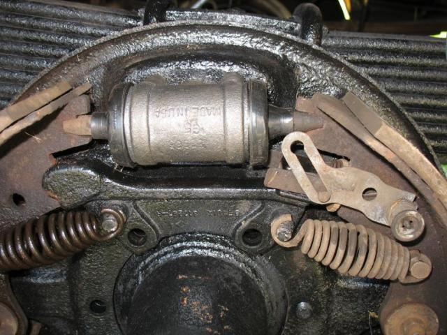
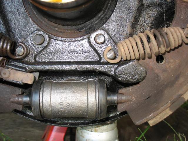
GENERAL INFORMATIONThe hydraulically-actuated rear wheel brake is a two-shoe, double-acting, non-servo floating type brake with an adjusting screw for each shoe. Two double piston wheel cylinders are used in this design and are equally effective in the forward and reverse directions (Fig. 1). On the Twinplex wheel brake assembly, the shoes anchor at either toe or heel, depending on the direcnon of drum rotation; thus they are always forwardacting and provide equal braking effort regardless of the direction in which the vehicle is moving. Brake anchor supports have removable slot anchor pins and/or keys at the shoe heel, and adjusting screws at the shoe toes, which act as anchors in the reverse direction of rotation. Each adjusting screw is threaded into or out of its support by means of a star wheel, as required, to establish proper lining clearance. The selfadjuster mechanism slides up a ramp and automatically maintains correct shoe-to-drum clearance. When brakes are applied, thrust is applied equally to all four shoe ends by the wheel cylinder pistons. Shoe contact with the drums causes the shoes to move with the drums until the leading ends butt against the anchor brackets in forward braking or against the adjusting pins in reverse braking. The shoe ends are free to move laterally on the angular abutment or adjusting screw surfaces. Since lining friction tends to force the trailing ends of the shoes into the drum, considerable added force is derived from this self-energizing action (Figs. 1 and 2). |
 Rear Wheel Duo-Servo brake |
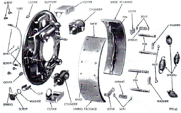 Figure 1 - Two Cylinder Floating Shoe Brake (Disassembled) |
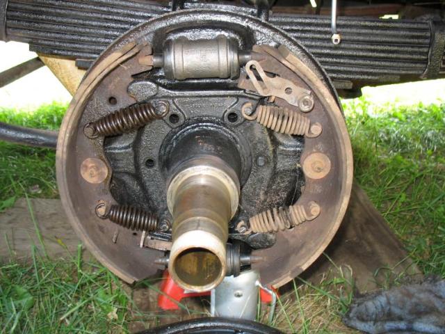
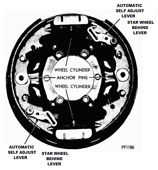 Figure 2 - Two Cylinder Hydralic Brake Assembly 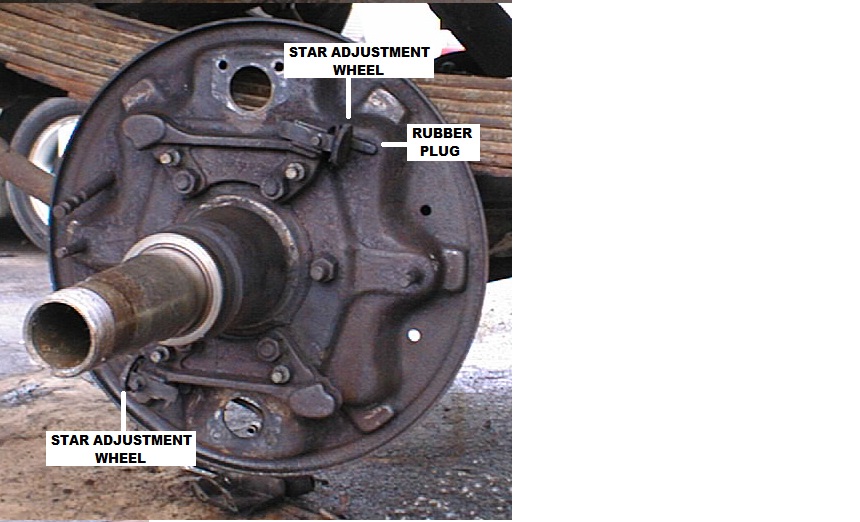 Figure 2a - Upper Brake Star Adjuster |
|
This brake assembly is used as follows:
|
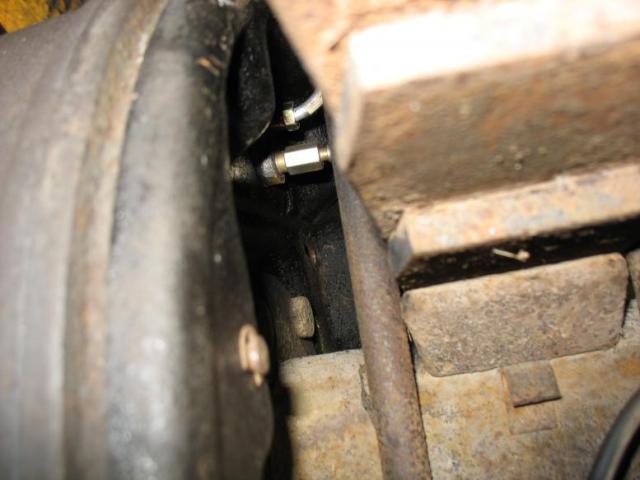
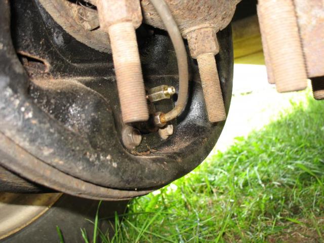
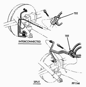 Figure 3 - Rear Wheel Brake Lines |
SERVICE PROCEDURES |
|
BRAKE SHOESRemoval
Installation
For best results, new linings on shoes should be ground (not bulfed). If this is not done, proper lining to drum contact may not be attained after normal run in. Adjustment (lf Required)Adjustment for lining wear is made by reducing excessive working clearance between lining and drum. For maximum safety, manual or booster powered brake systems require adjustment when brake pedal reserve is reduced to 2 or 3 inches, that is when the pedal drops to within 2 to 3 inches of the floor board, on a hard brake application.
|
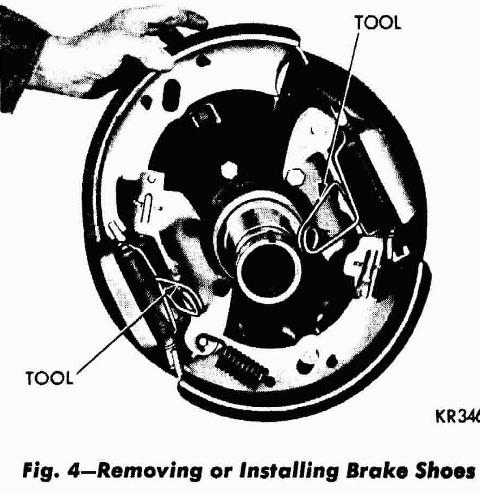 Figure 4 - Removing or Installing Brake Shoes 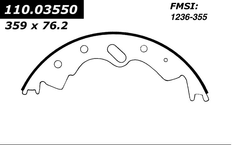 Twinplex Brake Shoe (FMSI 1236-355) 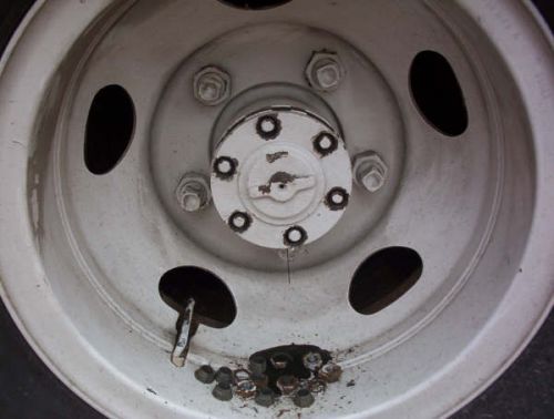 Axel Nuts, Washers, Cones Removed 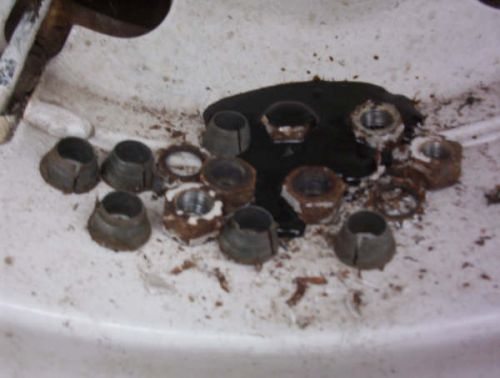 Closeup - Axel Nuts, Washers, Cones 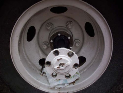 Removing Axle 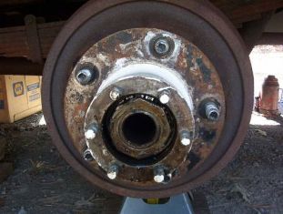 Axle Removed |
 Axle and Drum Removed |
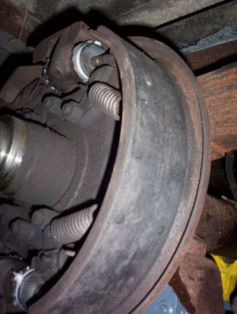 Side View of Brake Assembly |
 Upper Wheel Cylinder |
 Lower Wheel Cylinder |
 Upper Cylinder Bleeder Valve |
 Lower Cylinder Bleeder Valve |