Dave's Place
Apache Gear Train Lubrication
A special thanks to Dick Habegger for putting this information together
Before reading the instructions on HOW to do this, please see this note from Tim Schaefer,
the master Apache gearbox re-builder extraordinaire on WHY you'd want to do this in the first place:
People don't really understand that if the gearboxes are regularly cleaned and lubricated that they will last forever. There is no real force being put on them to lift the chains and roof. But, also, if the extension poles are also not lubricated correctly it will bind and put force in the system and mess things up. The biggest problem I see with the chains is the metal cable that holds them together. It is at the point in there life that they are rusting and snapping. This problem also dates back to the poles not being lubricated. If a regular schedule of lubricating the extension poles for the roof was followed, the spray lubricant would have got into the links and to the metal cables and protected them with the silicone. Ah, but what are we to do now! Hind sight is always 20/20.
The reason the old gearboxes give way is the small gears can't take much force when the system is poorly maintained. If maintained and lubricated correctly, these small teeth gearboxes would last forever. As far as the aluminum gears vs. poly carbonate gears, there is good and bad both ways. Poly carbonate gears will give when the temps are low in conjunction with bad lubrication. Also, it matters the grease that is used. I prefer a white lithium grease because of it's light weight and water resistant qualities, but it still thickens in colder temps. The aluminum gears will power thru where the poly carbonate gears break and give way. This means if the system binds at some point, the aluminum gears will keep turning and the system will break at a different point, usually the chains or the cable running thru the chains. It's all trade offs. The best thing to do here is understand the lift system and care for it accordingly.
Gearbox Repair Instructions on CD
For all of you who have lifting problems this CD is a must. It is in Microsoft Powerpoint format and will guide you step by step through the gear box. Filled with simple instructions, color photographs and diagrams to help you understand the lifting and lowering process. If your roof is lifting uneven, making a clunk, clunk noise or is just plain hard to crank, than this is exactly the cure you need. Don't spend your hard earned money on a new gear box when in most cases a little bit of maintenance is all that is needed, and this CD will show you how.
You can order via paypal at http://www.paypal.com using my email address or e-mail me directly at tschaefer26@comcast.net
The CD is $14.95 + $3.85 shipping. If you are not a Paypal user and would like more information, please go to this link: http://www.paypal.com/cgi-bin/webscr?cmd=p/gen/about-outside
Tim Schaefer
NOTE:
The 1972 Apache models had composition (molded) gears. The 1973 Apache gears were changed to metal parts.
Please refer to pages 3, 4, & 5 of the
"67-86 Apache Lift Systems Repair Manual". We will expand on the inspection, disassembly, cleaning,
lubricating and reassembly of the gearboxes and connecting tube.
 DESCRIPTION
There are two gearboxes; one is located in the rear of the trailer and has the crank handle connection in
the back of the gearbox. The second gearbox is located in the front of the trailer and has the connecting
tube tension spring assembly in the back of the gearbox.
INSPECTION
Before removing the gearboxes, inspect the assemblies for damage and binding. Look for cracked housings,
broken bolts, missing nuts and washers, rust, dents and wear. In particular, the connecting tube may need
cleaning, rust removal, and lubrication (bearing grease) at the frame suspension points. The tube ends fit
into roll pins on the driveshafts of the gearboxes. Check these pins and the tube ends for wear.
PARTS AND SUPPLIES
- Dow Corning 33 Lubricant Bearing Grease (contains silicone and lithium)
- Cleaning solvent
- Emery cloth (to clean off rust on shafts and tube)
- RTV Silicone Adhesive
- Roll pins (2) for gearbox drive shafts (if needed)
- Cotter pin (1), 3/16" diameter, 2-1/2' long
- Washer, stainless steel (2), 1/4" I.D.
- Washer, stainless steel (1), 3/4" to 7/8" I.D. 1-1/2" to 2" O.D., 1/16" thick, or Washer, galvanized (2), electrical box reducing washers
- Rubber grommet or washer, 3/4" I.D., 1/8" to 3/16" thick
- Nuts and washers for gearbox mounts, 1/4" x 20
TOOLS
- Wrench, or socket, 7/16"
- Wrench, or socket, 3/8"
- Bit, S2 (square no. 2 to fit socket adapter or driver)
- Hammer, ball-pein
- Punch, pin (or a large nail with the point flattened)
- Scraper
- Lint free rags
- Toothbrush
- Parts cleaning bucket
Procedure
- GEAR-TRAIN SYSTEM DISASSEMBLY
- Place top (Road Cover) in the full-down (towing) position (Do not perform this operation with the top up).
- Remove the skid plate protecting the rear gearbox.
- Remove the hardware from the front gearbox. Apply pressure on the spring-loaded connecting shaft to
disconnect it from the gearbox driveshaft. Lower the gearbox and pull away from the mounts. Release the
spring pressure from the connecting tube. Pull the connecting tube forward to disengage it from the rear
gearbox driveshaft. Place permanent identifying marks (position, location and which gearbox) on the gearbox.
CAUTION: Cleaning may remove these marks. - Remove the rear gearbox hardware and then lower the gearbox. Place permanent identifying marks
(position, location and which gearbox) on the gearbox.
CAUTION: Cleaning may remove these marks. - Look up into each chain opening (where the gearbox was located). Use a felt-tip marker and mark the
locations of each chain cog. This will help you remember where the cogs are located when you reinstall
each gearbox. Also, this is a good time to do the cleaning, rust removal and lubrication (bearing grease),
of the connecting tube, at the frame suspension points. Add grease to the connecting tube spring tension
assembly (for rust prevention). Leave the connecting tube in place.
-
 FRONT GEARBOX DISASSEMBLY
 - Mark, or otherwise identify the gear-tooth (contact points to the chain cogs) locations in relationship to the gearbox housing. Also, note each end of the gearbox and driveshaft. It is easy to be confused with the gear arrangement when you reassemble the housing.
- Remove the roll pin from the driveshaft with a pin punch and hammer. Set the roll pin aside.
- Clean the residue gasket material from the housings. Solvent-clean the housings.
- Remove the hardware from the gearbox housing with a 3/8' wrench and S2 bit driver.
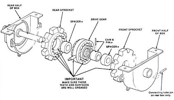
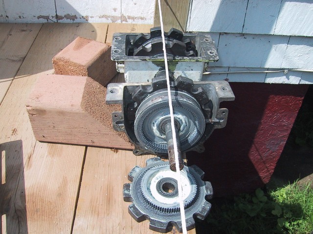
- Carefully pull the two housings apart and note (a digital photo will do) the location of each
seal, bearing, and gear. (This must be known for reassembly.)
New Style Gearbox
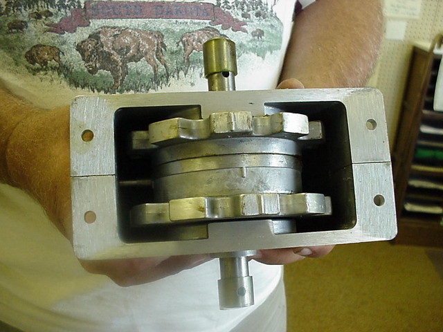
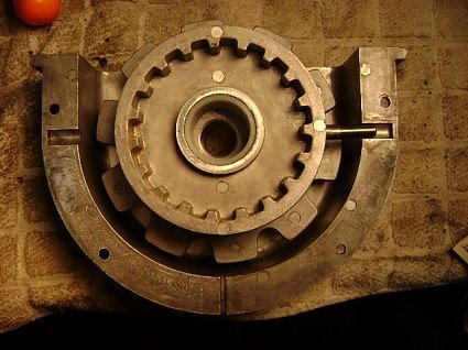
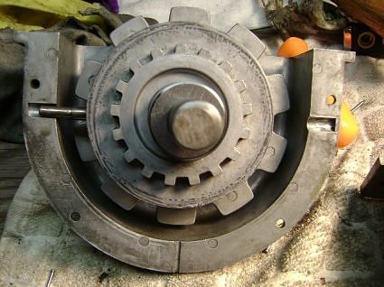
Old Style Gearbox
- Take each section of gears and remove all of the old grease and debris. A pan of solvent and toothbrush are good to use. Work the solvent into the roller bearings until the bearings will rotate. They might be frozen by the old grease.
- If the bearings will not turn, force a small amount of the bearing grease around each roller with your fingers. Repeat using solvent to clean the bearings. Continue this procedure until the rollers will turn. Repeat this method with each assembly. Again, note the location of each part in reference to its position in the gearbox.
- Repeat the cleaning procedure with the driveshaft bearings located in each housing. The bearings may have separated from the housing, when the gears were removed. Take note of the bearing and seal locations.
- FRONT GEARBOX ASSEMBLY
- Relubricate all of the bearings and the driveshaft.
- Add a film of grease over the teeth of each gear.
- Check the orientation of each part and match it to your drawings or photos. Slide each assembly together.
- Rotate the parts in either direction until the teeth engage and the housing shells can be pushed back together.v
- When you are satisfied that the housings can be completely closed, run a small bead of RTV adhesive around the mating portions of the gearbox housing shells. Smooth and remove any excess adhesive with your fingers and then reinstall the hardware on the housing. Do not seal the drain hole.
- Reinstall the roll pin on the driveshaft. Use the same pin that was removed, or a new one of the same size.
- Set the gearbox assembly aside.
- REAR GEARBOX DISASSEMBLY
- Mark, or otherwise identify the gear-tooth (contact points to the chain cogs) locations in relationship to the gearbox housing. Also, note each end of the gearbox and driveshaft.
- Remove the roll pin from the driveshaft with a pin punch and hammer. Set the roll pin aside.
- Remove the crank guide pivot pin.
- Follow the same procedures as used to disassemble the Front Gearbox; steps III.B through III.G.
- REAR GEARBOX ASSEMBLY
- Follow the same procedures as used to assemble the Front Gearbox; steps III.A through III.G.
- Set this assembly aside.
- FINAL ASSEMBLY
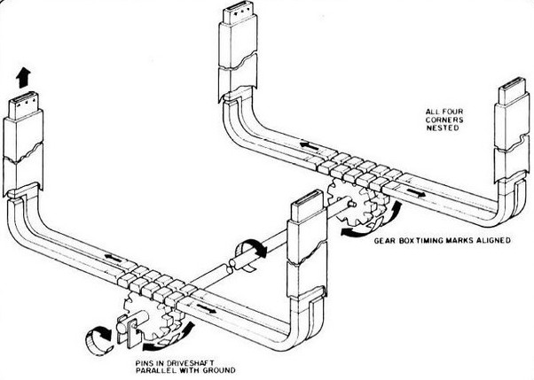
- Position the gearbox teeth (that the chain cogs will drop into) in the rear gearbox so they will be in the same alignment as you marked.
- Place the gearbox into its position, on the trailer, to see if the chain cogs fit into the gearbox. If so, reinstall the gearbox to the mounting screws with the hardware. If not, rotate the shaft of the gearbox so they will align with the cogs.
- It is time to reinstall the crank guide assembly to the back driveshaft. If any of the parts are broken, or missing then follow the suggested modification:
- Install the rubber washer over the back driveshaft and push forward.
- Install the stainless steel washer, or the two thin reducing washers.
- Take the crank guide bracket, cotter pin, and two 1/4" s.s. washers and place them
onto the driveshaft.
The correct order is: cotter pin, washer, right side of the bracket, driveshaft, left side of the bracket, washer, and cotter pin forked end. - Spread the cotter pin forks outward.
- Repeat steps VI.A and VI.B, for the front gearbox. Except, do not permanently mount the box to the trailer. Set the front gearbox on the ground.
- Reinstall the connecting tube onto the driveshaft of the rear gearbox and engage into the roll pin.
- Take the front gearbox and the connecting tube spring tension assembly; fit them together as you reinstall the gearbox to the mounting screws, on the trailer, with the hardware.
- You are now ready to use the crank and extend the trailer top. If all goes well, you will find that there is far less cranking "muscle" required. If this is not the case, consider improper alignment during the reassembly. Or, the chain and/or rails may be worn, or damaged. Follow other recommendations given for this condition as it goes beyond the scope of this document.
CAUTION:
There drive gear rides on needle bearings. Ensure you place a a container
under the gear gearbox to capture any needle bearings that may fall out during disassembly.
 NOTE:
NOTE:
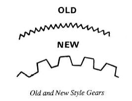
Do not use any sharp tools, or cloths that will leave lint. Also, observe the
type of gears that are used (old or new style). Refer to the picture of the old/new gear styles.
Place a check mark on the drawing next to the style of the gears that you have.
CAUTION:
The gear ratios are different between the old and new style gearboxes.
You cannot mix old and new stle gearboxes.
NOTE:
The grease goes on the internal gears only (Refer to picture above). it is important to keep the grease off
the chains and sprockets (The teeth that actually engage the chain). If you get grease on the sprockets
then they can slip and the top will not raise.
NOTE:
The 1972 APACHE has a peined-pin that holds the crank guide in place.
I found that I had to grind off the end of the pin, and remove the pin, before I could disassemble the
gearbox housing. Probably, the rubber washer and spring have deteriorated and are not longer installed.
This is the reason for the replacement items listed in the PARTS AND SUPPLIES list.
NOTE:
Realignment will be necessary if the chains have been moved during the
lubrication process, or, if the chains were not in the correct position. Try to reposition the chain cogs
in the center of their travel. And/or rotate the driveshaft, in small increments, to realign the gearbox.
This step is the most critical of all of the process. Unless it is performed correctly, the chain will
not extend the top (Road Cover), to a level position. Take your time and, if necessary, relax and try it
again, later.
NOTE:
The crank guide bracket is installed with the flat sides toward the
housing. Leave a 1/8" gap between the driveshaft and washer (Later, it will be divided to 1/16" for
each side of the driveshaft.) This is for a gap that will allow the crank sleeve to fit onto the
driveshaft, without excessive force. Now, bend the forks to a 90-degree angle of the cotter pin.
Cut off any part of the cotter pin fork that extends beyond the bracket.
Copyright, 2000 Associated Medical Electronics
Use and copying this document is authorized to anyone associated with, or owns, an APACHE trailer,
as long as the document is given the proper acknowledgement of the copyright owner.
April 9, 2000
Please report any errors or omissions to:
Dick Habegger
Associated Medical Electronics
4932 Budlong Street
Anaheim, CA 92807
amej@pacbell.net