Dave's Place
Dodge Electronic Ignition
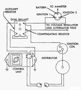
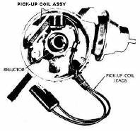
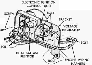
This system consists of a special pulse-sending distributor, an electronic control unit, a two-element ballast resistor, and a special ignition coil. The distributor does not contain breaker points or a condenser, these parts being replaced by a distributor reluctor and a pick-up unit. It was used from then on in all Dodge Class A motorhomes (M300-M600)
|
||

|
|
|
|
||
|
|
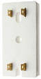
Ballast Resistor
|
|
|
|
Coil
|
|
|
Distributor
|
|
|
|
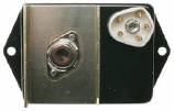
Electronic Control Module (ECM)
|
|
Operation
The ignition primary circuit is connected from the battery, through the ignition switch (I1), through the primary side of the ignition coil, to the control unit (pin 2) where it is grounded.
The secondary circuit is the same as in conventional ignition systems: from the secondary side of the coil, the coil wire to the distributor, the rotor, the spark plug wires, and the spark plugs.
The magnetic pulse distributor is also connected to the control unit. As the distributor shaft rotates, the distributor reluctor turns past the pick-up unit. As the reluctor turns past the pick-up unit, each of the eight teeth on the reluctor pass near the pick-up unit once during each distributor revolution (two crankshaft revolutions since the distributor runs at one-half crankshaft speed). As the reluctor teeth move close to the pick-up unit, the magnetic rotating reluctor induces voltage into the magnetic pick-up unit. This voltage pulse is sent to the ignition control unit from the magnetic pick-up unit (pins 4 and 5).
When the pulse enters the control unit, it signals the control unit to interrupt the ignition primary circuit. This causes the primary circuit to collapse and begins the induction of the magnetic lines of force from the primary side of the coil into the secondary side of the coil. This induction provides the required voltage to fire the spark plugs.

The advantages of this system are:
- The transitors in the control unit can make and break the primary ignition circuit much faster than conventional ignition points.
- A higher primary voltage can be utilized since this system can be made to handle higher voltage without adverse effects, whereas ignition breaker points cannot.
- The quicker switching time of this system allows longer coil primary circuit saturation time and longer induction time when the primary circuit collapses. This increased time allows the primary circuit to build up more current and the secondary circuit to discharge more current.
Firing order diagram for 440-3 engine:
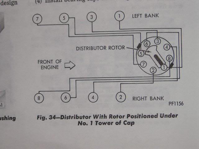
Firing Order
For all Dodge V-8 Motorhome engines: 1-8-4-3-6-5-7-2
Left side cylinders are numbered (from front) 1-3-5-7
Right side cylinders are numbered (from front) 2-4-6-8
The point at which each spark plug fires is variable and is controlled by:
- Initial Timing Advance setting
- Mecanical Advance
- Vacuum Advance
Initial Timing Advance setting
This is the reference point upon which all engine timing is based. Timing advance is required because it takes time
to burn the air-fuel mixture. Igniting the mixture before the piston reaches top dead center (TDC) will allow the
mixture to fully burn soon after the piston reaches TDC. If the air-fuel mixture is ignited at the correct time,
maximum pressure in the cylinder will occur sometime after the piston reaches TDC allowing the ignited mixture to
push the piston down the cylinder with the greatest force. If the ignition spark occurs at a position that is too
advanced relative to piston position, the rapidly expanding air-fuel mixture can actually push against the piston
still moving up, causing detonation and lost power. If the spark occurs too retarded relative to the piston position,
maximum cylinder pressure will occur after the piston is already traveling too far down the cylinder. This results
in lost power, high emissions, and unburned fuel.
1973 (Electronic Ignition)
318 - 2.5 +/- 2.5 Degress BTDC
413 - 5.0 +/- 2.5 Degress BTDC
440 - 7.5 +/- 2.5 Degress BTDC
1974 and later
Typically the same as 1973 however, you have to refer to the Emissions Label on the Valve Cover.
Note:
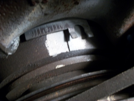
Seeing the timing marks and reference plate on a 440-3 can be difficult. You normally have to turn the front wheels
to the left and get up inside the right front wheel well to see the timing marks. Even then, you may have to unbolt
the radiator overflow container and move it out of your way to see the timing marks.
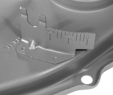
440-3 Timing tab mounted on timing cover:
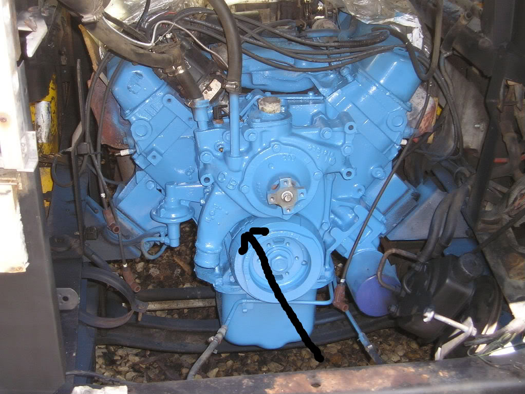
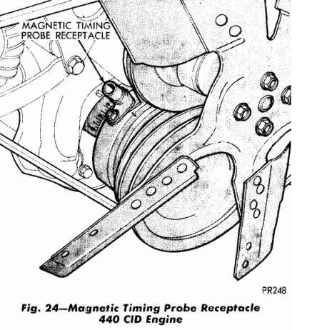
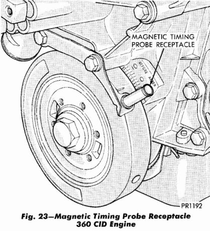
Location of timing tab on front of engine (360 tab is located on drivers side of water pump):
Close up of a 440-3 Timing tab aligned with timing marl on harmonic balancer:
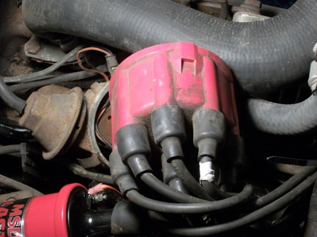
Rotor position with #1 cylinder at TDC on compression stroke (pointing at alternator):
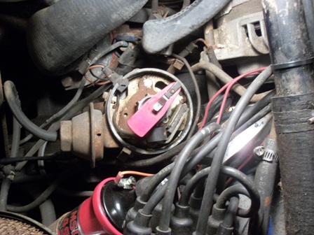
Relationship of #1 plug wire (white tape) to distributor cap hold down clamp:
79 and later 440-3 timing tab:
360 timing tab:
Mecanical Advance
Ignition timing has to become increasingly advanced (relative to TDC) as the engine speed increases so that the
air-fuel mixture has the correct amount of time to fully burn. As the engine speed increases, the time available
to burn the mixture decreases but the burning itself proceeds at the same speed, it needs to be started increasingly
earlier to complete in time. An increasing mechanical advancement of the timing takes place with increasing
engine speed. This is possible by using the law of inertia. Weights and springs inside the distributor rotate and
affect the timing advance according to engine speed by altering the angular position of the timing sensor shaft
with respect to the actual engine position. This type of timing advance is also referred to as centrifugal timing
advance. The amount of mechanical advance is dependent solely on the speed at which the distributor is rotating.
Vacuum Advance
The second method used to advance the ignition timing is called vacuum timing advance. It increases fuel economy
and driveability, particularly at lean mixtures. A vacuum chamber on the side of the distributor automatically
varies the instant at which the spark occurs as a function of manifold vacuum. Vacuum advance provides the additional
advance that is needed when the engine is operating at part throttle. At part throttle less air-fuel mixture gets
into the cylinders and the mixture takes longer to burn after it is ignited. Because the mixture burns more slowly,
the piston will be past top dead center and moving down before the mixture has a chance to burn and produce high
power. As a result much of the power in the fuel will be lost. The vacuum advance mechanism consists of a flexible
spring-loaded diaphragm connected by a linkage to a plate on which the magnetic pick-up is mounted (breaker plate
on which the points are mounted for non-electronic ignition systems). The sealed side of the diaphragm is connected
by a tube to the carburetor . The throttle valve (butterfly) is below the vacuum passage (port) in the carburetor
air horn so there is no vacuum advance when the engine is idling because the throttle is closed. However, when the
throttle is partly open, intake manifold vacuum pulls the diaphragm in and this causes the breaker plate to rotate a
few degrees and advance the timing . With wide-open throttle there is very little vacuum in the intake manifold so
there will be no vacuum advance. In most instances the vacuum advance is disconnected before checking the timing and
point gap (non-electronic ignition systems).
In summary:
- No Vacuum Advance at idle.
- No Vacuum Advance at wide open throttle.
- Vacuum Advance system is intended for emissions control, driveability, and fuel economy.
Vacuum advance plate action:
In response to emission control requirements, in 1974 Dodge added a emission control sytem which senses engine temperature in order to regulate the vacuum advance system when the engine is hot or cold. This system increases the advance when the engine is cold by allowing engine manifold vacuum to also be used when the engine is cold. Once the engine is warmed up, normal ported vacuum is used. At low temperature the advance allows the enriched warm-up mixture to burn more completely, providing better and cleaner cold-engine running.
Start vs Run
Start
- When the ignition key is placed in the START position, battery voltage is supplied to both the I1 and I2 leads.
- The I1 lead provides voltage to the AUX side (5.0 Ohm) of the Ballast Resistor and to pin 1 (primary power input) of the ECM .
- The output of the AUX resistor is applied to ECM pin 3 and is used for electronic circuit stablization.
- The I2 lead provides voltage to the output side of the Compensating Resistor (0.5 Ohm) section of the Ballast Resistor therfore the Compensating Resistor is bypassed during starting allowing full battery supply voltage is then applied to the plus (+) side of the Coil.
- The minus (-) side of the coil is connected to pin 2 of the ECM. The ECM (via pin 2) controls electrical current flow through the coil. Electrical current will flow through the coil until the the distributor pick-up (ECM pins 4 and 5) signals it is time to fire the spark plug.
- The ECM then shuts OFF the current flow which causes the magnetic field in the coil to collasp.
- This results in a high voltage pulse being routed to the spark plug via the coil wire, distributor cap, rotor and spark plug wire.
- After a predetermined amount of time (designed into the ECM circuitry) the ECM will turn the current back ON to the coil.
Run
- When the ignition key is placed in the RUN position, voltage is supplied to just the I1 lead.
- The I1 lead provides voltage to the AUX side (5.0 Ohm) and the Compensating side (0.5 Ohm) of the Ballast Resistor and to pin 1 of the ECM.
- Since there is no voltage from the igniition switch on I2, the voltage (reduced) applied to the coil is via the Compensating Resistor.
- The remaning operation is identical to the START position.
CAUTION
Bypassing (jumpering around) the Compensating Resistor for extended periods of time will
damage the ECM.
Carry a spare Ballast Resistor in your on-board toolkit instead.
Notes:
- The Ballast Resistor is a high failure item. Most people carry a spare Ballst Resistor with them.
-
 Corroded wiring connectors and solder joints will reduce voltage to the ignition circuitry resulting in hard
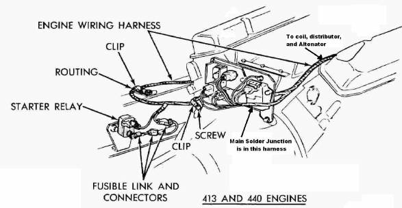
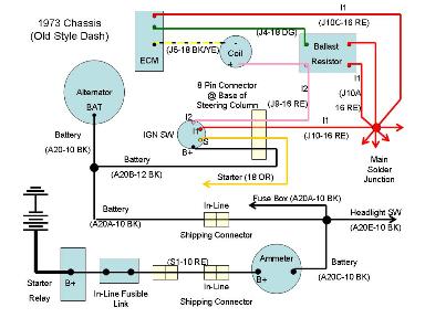
starting and phantom problems. In the wiring harness drawing above, take note of the location of the Major
Solder Junction reference as it is the main distribution point for ignition and charging circuitry.
Corroded wiring connectors and solder joints will reduce voltage to the ignition circuitry resulting in hard
starting and phantom problems. In the wiring harness drawing above, take note of the location of the Major
Solder Junction reference as it is the main distribution point for ignition and charging circuitry.
You can see by this drawing of a 1973 chassis, there are many connections and solder joints between the battery and the Ballast Resistor/ECM Module. Corrosion, overstressed wiring (high current), and age all factor in resulting in voltage drops. The in-line fusible links located at the starter relay weaken with time due to current draw. - For reference, basic operation of the Multiple Spark Discahrge (MSD) system is based on the same principles as the MOPAR system. Hookup is a little different (no ballast resistor) and the MSD fires a spark plug multiple times but the system is still triggered by a pick-up sensor and controls current flow through the coil. The deference is that it turns the coil off and on multiple times for each firing pulse.
| Year/Engine | Distributor | Cap | Rotor | Points | Elec Ign Pick-up |
Advance | Coil | Balance Resistor |
Ign Module (ECM) |
|---|---|---|---|---|---|---|---|---|---|
| 1969-71 318 (w/o Elec Ign) |
2875805 | 2444507 Echlin MO20 |
1838516 Echlin MO13 |
2098244 Echlin CS851 |
N/A | 2875806 | 2495531 Echlin IC12 |
2275590 Echlin ICR12/ICR13 |
N/A |
| 1972 318 (w/o Elec Ign) |
3656295 | 2444507 Echlin MO20 |
1838516 Echlin MO13 |
2098244 Echlin CS851 |
N/A | 3438424 Echlin VC3008 |
2495531 Echlin IC12 |
2275590 Echlin ICR12/ICR13 |
N/A |
| 1969-77 318 (with Elec Ign; w/o ERS) |
3656686 | 2444507 Echlin MO20 |
1838516 Echlin MO13 |
N/A | 3656738 Echlin MP804 |
3656682 | 2495531 Echlin IC12 |
3656199 Echlin ICR24 |
3755550 Echlin TP50 |
| 1969-77 318 (with Elec Ign; with ERS) |
3656673 | 2444507 Echlin MO20 |
1838516 Echlin MO13 |
N/A | 3656738 Echlin MP804 |
3656766 Echlin VC3031 |
2495531 Echlin IC12 |
3656199 Echlin ICR24 |
3755550 Echlin TP50 |
| 1976 360 (with Elec Ign) |
3656673 | 2444507 Echlin MO20 |
1838516 Echlin MO13 |
N/A | 3656738 Echlin MP804 |
3656766 Echlin VC3031 |
2495531 Echlin IC12 |
3656199 Echlin ICR24 |
3755550 Echlin TP50 |
| 1970-71 413 (w/o Elec Ign) |
2875986 | 2444507 Echlin MO20 |
1838516 Echlin MO13 |
2098244 Echlin CS851 |
N/A | 2875768 | 2495531 Echlin IC12 |
2275590 Echlin ICR12/ICR13 |
N/A |
| 1972 413 (w/o Elec Ign) |
3656366 | 2444507 Echlin MO20 |
1838516 Echlin MO13 |
2098244 Echlin CS851 |
N/A | 2875768 | 2495531 Echlin IC12 |
2275590 Echlin ICR12/ICR13 |
N/A |
| 1973 413 (w/o Elec Ign) |
3656835 | 2444507 Echlin MO20 |
1838516 Echlin MO13 |
2098244 Echlin CS851 |
N/A | 3656828 | 2495531 Echlin IC12 |
2275590 Echlin ICR12/ICR13 |
N/A |
| 1972 413 (with Elec Ign) |
3656686 | 2444507 Echlin MO20 |
1838516 Echlin MO13 |
N/A | 3656738 Echlin MP804 |
3656682 | 2495531 Echlin IC12 |
3656199 Echlin ICR24 |
3755550 Echlin TP50 |
| 1973 413 (with Elec Ign) |
3656840 | 2444507 Echlin MO20 |
1838516 Echlin MO13 |
N/A | 3656738 Echlin MP804 |
3656833 | 2495531 Echlin IC12 |
3656199 Echlin ICR24 |
3755550 Echlin TP50 |
| 1971-76 440 (with Elec Ign) |
3656158 | 2444507 Echlin MO20 |
1838516 Echlin MO13 |
N/A | 3656738 Echlin MP804 |
3656310 Echlin VC3028 |
2495531 Echlin IC12 |
3656199 Echlin ICR24 |
3755550 Echlin TP50 |
| 1977 440 (with Elec Ign; w/o ERS) |
3755158 | 2444507 Echlin MO20 |
1838516 Echlin MO13 |
N/A | 3656738 Echlin MP804 |
3656310 Echlin VC3028 |
2495531 Echlin IC12 |
3656199 Echlin ICR24 |
3755550 Echlin TP50 |
| 1977 440 (with Elec Ign; with ERS) |
3755888 | 2444507 Echlin MO20 |
1838516 Echlin MO13 |
N/A | 3656738 Echlin MP804 |
3874891 | 2495531 Echlin IC12 |
3656199 Echlin ICR24 |
3755550 Echlin TP50 |
| « Basic Air / Fuel Theory | Maintaining a MOPAR Distributor » |